Introduction
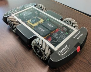
While working for ElectroCraft I was tasked with creating a demonstration robot to show off ElectoCraft’s MPW52 product (BLDC motor + planetary gearbox) and Complete Power Drive.
The intent was to emulate typical AGV (automated guided vehicle) and AMR (Automated Mobile Robot) use in warehouses. These are typically 2 or 4 wheel drive robots, capable of carrying loads on top.
The robot was designed with 4 MPW52 units and a drive for each axis. An extruded aluminum chassis, foam bumpers, and various mounting hardware was designed, and machined, watercut, or 3D printed.
With 4 wheels being driven, mechanum roller wheels allow both frontward/backwards and rotation, but also full translation in any 2D vector.
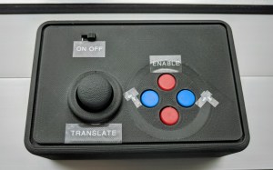
Since this robot was for demonstration purposes, no automation would be needed. Instead a wireless controller was included to command movements.
Motion Control and Wireless Communication
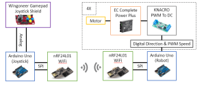
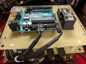
An Arduino microcontroller was implemented to act as a motion controller on-board the robot. A second Arduino is housed in the wireless controller. nRF24L01 chips provide wireless communication between the two Arduinos. The nRF24 Arduino library was used to control the wireless chips, which use SPI to communicate. A two-way communication was established between the wireless controller and robot. This provides some safety by disabling the drives if the robot loses communication.
At the time, the ElectroCraft BLDC drives did not have digital CAN communication (as they do now) so the analog input was used to command speed to each drive. To create the analog signal, the Arduino uses 4 PWM pins, each of which feed into a PWM to DC module.
The wireless controller uses a joystick shield which provided a easy to implement human interface with a joystick and a few buttons. These are exposed through the 3D printed controller housing.
Arduino Code
Controller Side
On the controller side, the Arduino is code:
- Reads the joystick and button states
- Provides debouncing on the button states
- Acts as the master in the wireless communication
- Packages the joystick and button state info and sends it to the robot side Arduino
Robot Side
On the robot side, the Arduino is code:
- Listens for motion commands from the wireless controller
- Performs scaling & normalizing of the joystick state
- Performs the kinematics calculations to transform user command to (4) axis speeds
- Outputs PWM signals for each axis
Kinematics
The robot Arduino takes in the user X, Y, and Z motion commands and transforms them into axis speeds by the following equations:

commands to individual axis speeds
In addition the basic formula above, if any axis is initially calculated to spin faster than a given maximum speed, the robot Arduino scales the motion profile down to valid speeds while maintaining the commanded direction.
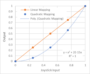
The robot Arduino also maps the user input quadratically to make it easier to command slow, controlled motion. In the figure below, the quadric mapping shows that less output is commanded at low command inputs: