I’ve created a number of scripts for AutoDesk Inventor which help to automate workflows and reduce error rates. These are programmed in VB.net and use the Inventor API. Inventor allows the user interface to by modified with buttons for these scripts (including a custom icon image file), which provides the user with quick, single click access.
In general, the scripts have error handling included to check user input and provide meaningful feedback if the script was not able to finish execution.
- Winding Diagram
- Inspection Numbers
- Inspection Sheet
- Secondary Units (For Tables)
- Revision Tools
- Export PDF and STEP Files
Winding Diagram

This script creates winding diagrams for 1-6 phase BLDC and stepper motors from user entered data by performing the following:
- Reads winding definition data from tables off to the side of the drawing (such that they don’t print)
- Generates a symbol and draws in the coils, jumper connections, and terminal connnections
- Color codes per phase
- Places text annotations and moves them if they interfere with other drawing objects
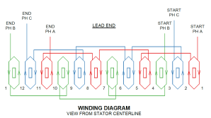

Additionally, if the data tables do not exist, the script will create them and exit so the user can enter data and re-run the script.
Inspection Numbers
As of Inventor 2023, there isn’t a way to turn inspection numbering on for all the annotations (e.g., dimensions, leader text, etc.) within a drawing at the same time. It requires a user to edit each annotation a turn on inspection numbering and drawing may have 30+ annotations. This has many draw backs:
- The time and effort to individually turn on inspection numbers for each annotation
- Since the user must enter a number for the inspection, the numbering usually ends up out of order on the sheet and is difficult to follow. Or worse, numbers are repeated or missing in the series.
- Some annotation types like chamfer notes, leader text notes, and surface finish symbols can not have a built-in inspection number added to them
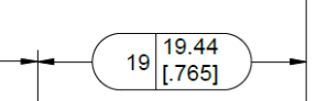
an inspection number (19) added
To overcome these limitations, this script automates all of the above and creates custom inspection numbers for those annotations that can not have a built-in one added. The script does the following:
- Collects all the annotations on a drawing
- Turns on inspection numbers for the annotation types that have the built-in capability
- For non-built-in inspections numbers: custom sized sketched symbols are created for each annotation
- Inspection numbers are set in order from left to right as the occur on the sheet, and the number continues from sheet to sheet

This is by far the most complex script listed on this page, including two classes, 20 functions, and 800+ lines of code.
Inspection Sheet

The Inspection Sheet script creates an Excel document from an Inventor Drawing with Inspection Numbers. This builds off the knowledge gained from the Inspection Numbers script.
For each of the annotations within a drawing, the nominal value, tolerance, modifiers, and text are recognized and used to create a row in the inspection sheet. Upper and lower limits are output, along with the modifiers and text annotations. Annotations are grouped by type. Importantly, the script also handles GD&T, exporting the control type, tolerance, and datums.
The script imports an Excel template file to base the export off of, and fills in the rows accordingly. A few metadata entries are also filled in by the script like part number and revision.

Secondary Units (For Tables)
Currently in Inventor 2023, drawings may be dual unit (e.g., mm [in]) for the length annotations, but the functionality is not included for tables. And in a drawing that has many configurations, lengths are commonly tabulated, which means the user has to convert the units themselves and enter these strings into a table manually.
This is needless grunt work, and worse, a potential source of error. So I created a script when runs when a table is selected to recognize columns where length conversions need to take place, performs the conversion, and modifies each cell accordingly.
Conveniently, if the data is new, the user simply needs to enter the primary value and a pair of square bracket “[]”, and the script will recognize these cells to convert. As both inch and metric primary drawings exist, the script will recognize the sheet format and perform the correct conversion.
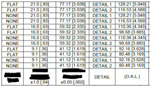
with tabulated lengths for various configurations of a part.
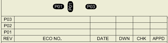
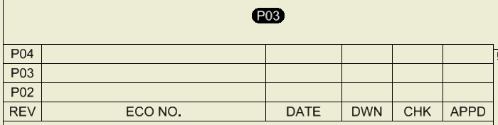
Revision Tools
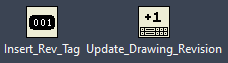
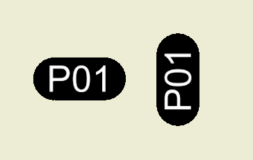
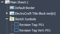
The Insert Rev Tag tool inserts symbols that show where an edit has taken place on a drawing that includes the current revision. The tag object is also given a meaningful name in the model tree. Previously this took many clicks and manual entry of the revision number. Additionally, the user can hold the CTRL key to place the symbol sideways to fit better.
The Update Drawing Revision tool updates the drawing revision by placing a new row in the revision table, entering the next numeric revision, and hides revisions older than the past three. The tool deletes any old revision tags at same time. Finally, the CTRL key can be held to change the numbering scheme from prototype numbers to productions numbers.

Export PDF and STEP Files
The Export PDF and STEP script can be run on any type of Inventor file (part, assembly, drawing) to export a 2D PDF file and/or 3D STEP file(s) depending on the file type. Additionally, the revision level is recognized and added to the of the filename.
This becomes especially convenient when dealing with iParts/iAssemblies, that may have 30+ configurations. The script will recognize these features and export all of the configurations STEP files.
