Introduction & Motivation
Brushless DC (BLDC) motors are three phase motors which require electrically controlled commutation (current in each of the three phases). To allow electrical commutation, typically three hall sensors are used to sense rotor position, creating 6 different hall states as the magnets on the rotor pass by the sensors.
For proper motor operation, current must flow in each of the three phases according to the hall states. Therefore, a commutation table defines current in each phase for each of the six hall states. However, there are a few arbitrary design choices (e.g., phase ordering circumferentially, winding direction of each coil, and hall sensor polarity) in the motor construction that can produce 1 of 12 different commutation tables.
https://www.digikey.be/nl/articles/controlling-sensorless-bldc-motors-via-back-emf
Therefore, it can be advantageous to have a device which can show which of the 12 commutation tables will correctly drive the motor. This device will take advantage of the back EMF generated by backdriving the motor with an external, second motor at a constant speed. This shows the relative position between hall sensors affixed to the stator and the phase locations within the stator.
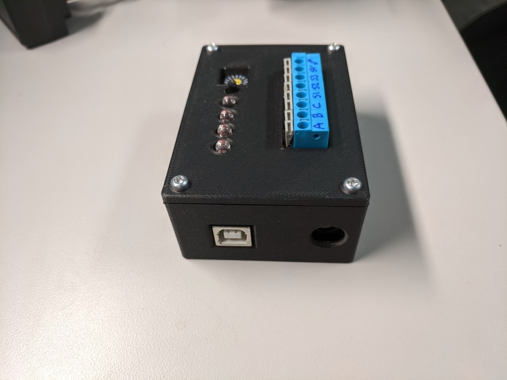
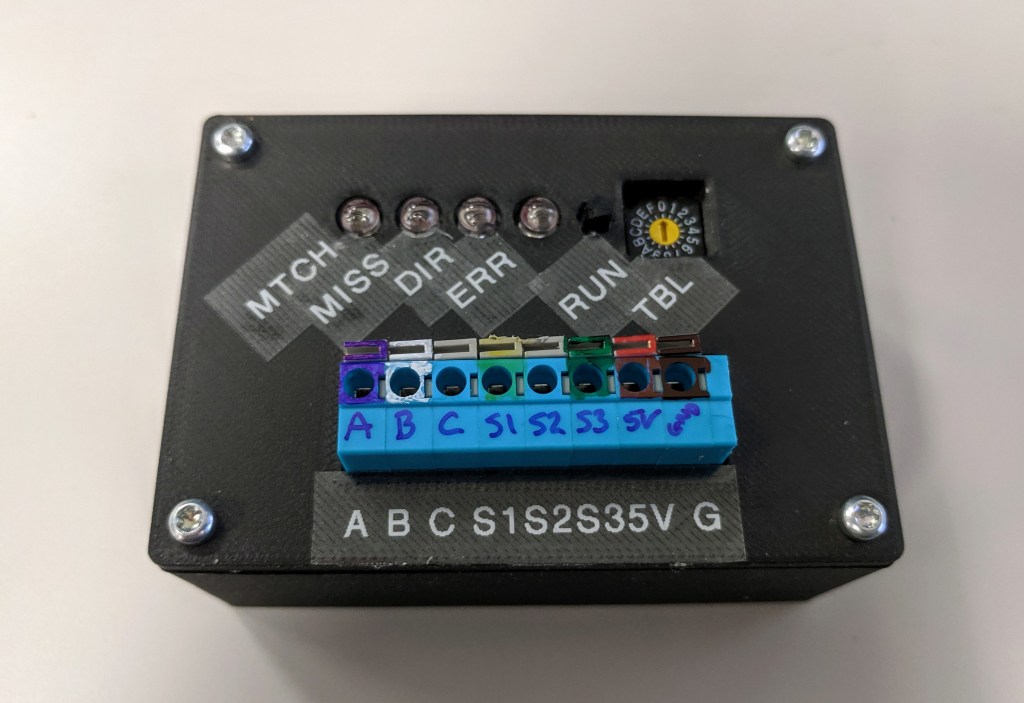
Below are some images of the completed device, built from an Arduino microcontroller, a quad comparator chip, some passive electrical components, and a custom designed 3D printed housing.
Device Design
Motor Interface
Motor Phases
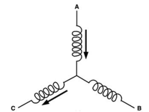
In a typical BLDC motor, the winding is wound in a “wye” pattern, meaning that the three phases are interconnected and only 3 lead wires are exposed to power the motor:
https://www.digikey.be/nl/articles/controlling-sensorless-bldc-motors-via-back-emf
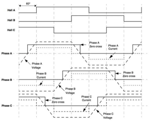
Therefore, when the motor is backdriven, the BEMF generated can only be measured as the difference between two phases (e.g., A-B, B-C, and C-A). These waveforms cycle between a positive and negative amplitude which presents a problem for simple measurement with the Arduino’s 0-5V analog inputs.
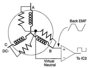
The trick is to create a “virtual” neutral, external to the motor. As an aside, this trick is used in sensorless BLDC drives. Sometimes hall sensors are omitted for cost, and the drive uses the BEMF measurement to determine the rotor position instead.
The virtual neutral is created by three equivalent resistors:
https://www.digikey.be/nl/articles/controlling-sensorless-bldc-motors-via-back-emf
With the virtual neutral, there is now a voltage to compare each of the three phase voltages to. A quad comparator chip can now simplify the data measurement to a High or Low digital signal, corresponding to whether the voltage on each phase is higher or lower than the virtual neutral, respectively.
Hall Sensors
The hall sensor measurement by the Arduino is trivial. The three hall sensor states are read directly by digital input pins.
User Interface
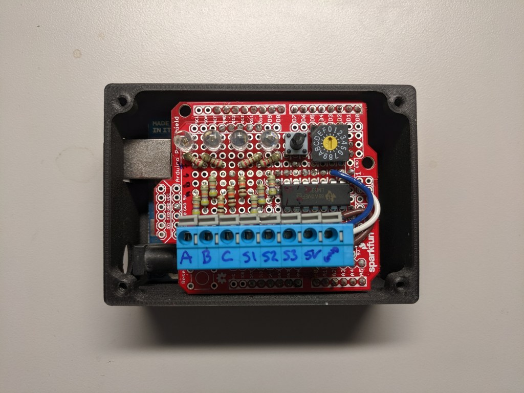
Spring terminals to connect each of the 8 leads of the BLDC motor to the device, two of which provide 5V power to the hall sensors. A rotary coded switch allows the user to select 1 of 12 commutation tables, which creates a 4 bit digital signal and is recorded by the Arduino to determine the selected position on the switch. Finally, a set of LED’s signal the results of the test.
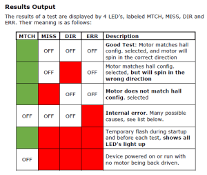
The LED’s indicate if the selected commutation table matches what was measured, if the direction was simply backwards, or if an error occurred (e.g., an invalid hall or phase state):
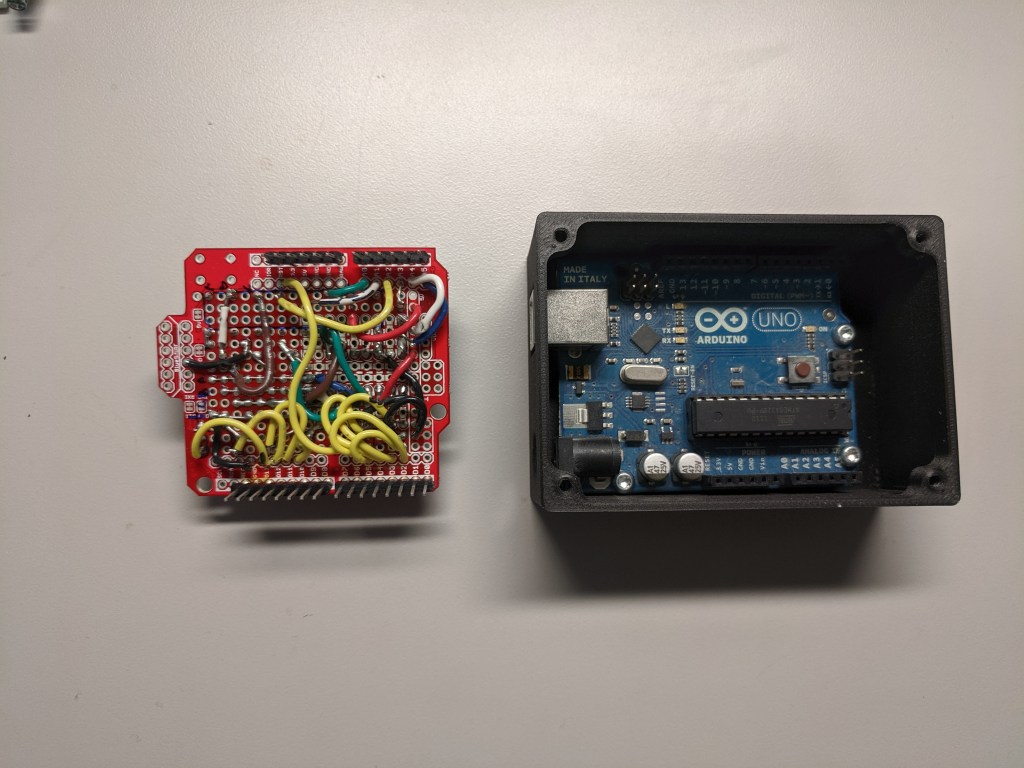
Prototype Shield
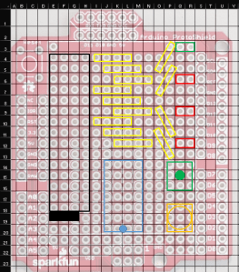
An excellent way to construct devices with the Arduino is to use pre-made shields. These connect to all the pin headers on the Arduino PCBA at the same time, breaking out the paths as needed. The simplest form of this is a plain grid of plated thru holes to make soldered connections to the device.
To layout and plan the connections on the solder-able shield, a image overlay was created in Excel, and the row/column sizes were adjusted 1:1 with the hole pitch in the shield:
Arduino Code
The Arduino first performs an initialization sequence, setting up pin modes and internal pull-up resistors. Then a function performs a short data acquisition , which measures the motor speed. The motor speed is used to adjust the following data acquisition to one electrical cycle of the motor. During the main data acquisition, the Arduino continually reads 6 digital inputs corresponding to the 3 hall sensors and 3 comparator outputs.
Post processing is then performed as follows:
- Loop through each of the 6 digital traces and find the indices corresponding to state changes
- Using the state change indices, determine a hall state ID number and a phase state at the middle of each of the commutation state
- Use the hall state data to determine motor spin direction and compare to known commutation tables
- Convert the phase state data to equivalent line-line state
- Build a motor ID: A 6 bit digit number, where each digit represents the line state and where it occurs in the state table
- Simple lookup to convert the motor ID to a commutation table number (1-12)
Finally, the comparison is performed from the user selected commutation table to the table determined from measuring the motor. LED’s are powered corresponding to the test results, and debug data is printed to the serial port.
